Introduction#
The Advanced Encryption Standard (AES) is a widely used block cipher encryption algorithm. One of my past projects called for the RTL implementation of a version of AES for both encoding and decoding. This blog post is a presentation of this Verilog project.

RTL implementaion of 128 bit Advanced Encryption Standard (AES) encyption algorithm
Advanced Encryption Standard (AES)#
Before we begin, here is a quick introduction to the AES algorithm :
The AES algorithm is a symmetric block cipher that can encrypt (encipher) and decrypt (decipher) information. Encryption converts data to an unintelligible form called ciphertext; decrypting the ciphertext converts the data back into its original form, called plaintext.
The AES algorithm is capable of using cryptographic keys of 128, 192, and 256 bits to encrypt and decrypt data in blocks of 128 bits. These different “flavors” may be referred to as “AES-128”, “AES-192”, and “AES-256”.
Our implementation is of the AES-128 flavor.
Overview of AES#
As mentioned earlier, AES is a block cipher algorithm, it encrypts/decrypts over multiple rounds. Each round will receive a 16 bytes data block and a key, and generate a new version of this data block, as well as a new key for the next round.
Let’s emphasize here that both the key and the data will be updated each round.
The key size determines the number of rounds. There are :
- 10 rounds for a 128 bit key
- 12 rounds for the 192 bit key
- 14 rounds for the 256 key.
Encrypting the data#
Encrypting a plaintext data block to ciphertext is done by applying the following transforms :
SubBytes, ShiftRows, MixColumns and AddRoundKey.
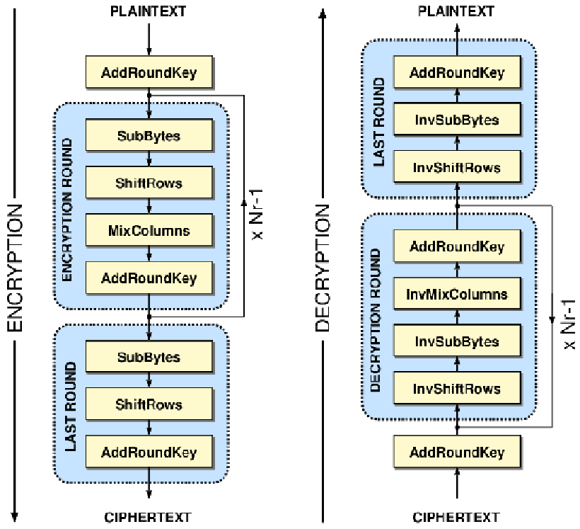
For the initial round, only the AddRoundKey transform is applied.
For the middle rounds, all the transforms are performed.
For the final round, only the SubBytes, ShiftRows and AddRoundKey transforms are applied.
We will elaborate more on these transforms later in the article.
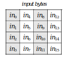
Internally the 16 data bytes are mapped onto a 4x4 byte matrix.
In the article, we will be using the row and column term to refer to the rows and columns of this matrix.
Key scheduling#
During each encryption round, a new key is computed based on the round index, and on the key used during this round.
This is called Key Expansion, and the algorithm that creates this new key for each round is called the Key Scheduler.
The new key is obtained by passing the last column of the old key though the following
transforms : RotWord, SubWord, Rcon, then xor-ing the result with the first column’s original value,
and then propagating this back through all the columns.
Decryption overview#
The AES algorithm can be inverted to perform the decoding operations. This is done by applying the inverse cipher transforms in reverse order.
Encryption#
SubBytes#
The SubBytes transform is a byte substitution based on a table called the S-box.
Each byte of the 16-bytes data block will be substituted by its S-box equivalent.
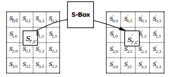
S-box to each byte of the dataThe substitution table is as follows with the x and y indexes corresponding to the hexadecimal
value of the xy data to be substituted.
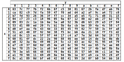
xy (in hexadecimal format).Most implementations store this table in memory and access it using the value for the byte to be substituted as an offset.
Because we are implementing this functionality in hardware and would ideally like each round to only take 1 cycle,
using this method would force us to implement 16 memories, each 256 entries deep and 8 bits wide to perform this operation in parallel.
To avoid that cost, we looked for a more efficient way.
It turns out that the S-box logic can be minimized, as shown by Boyar and Peralta in their
2009 paper A new combinational logic minimization technique with applications to cryptology.
Our S-box is a translation of the circuit they proposed in this paper.
The result is far from being human readable, but the produced output matches perfectly with the substitution table and is much cheaper logic-wise.
If the reader is as doubtful of the logic’s equivalence as I was when I implemented it, he can take a look at a test bench that I wrote to verify that equivalence.
ShiftRows#
The ShiftRows transform performs a left cyclical byte shift of each data row, with an offset based on the row’s index.
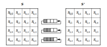
This transform is easily implementable in hardware.
MixColumns#
Unlike what this transform’s name might suggest, it isn’t as simple as shuffling columns.
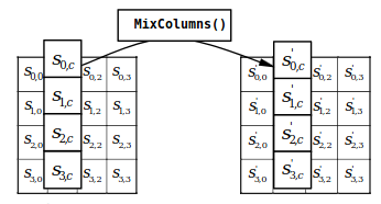
This transform takes each column, and treats it as a 4 term polynomial. This polynomial is then multiplied by a constant 4x4 matrix.


The catch here is that these operations are done in a Galois field and as such, the meaning of the “sum” and “product” operations are not the usual ones.
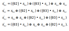
Because we are dealing with Galois field arithmetics all these operations can be implemented using basic
xor \(\oplus\) and and \(\bullet\) operations, and again, translate easily into hardware.
AddRoundKey#
This transform is a simple xor between each data column and the corresponding column of the current round’s key.
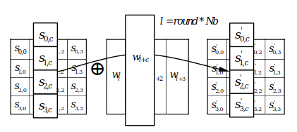
xor each column of the data with the corresponding column of the key, source : FIPS-197 Announcing the ADVANCED ENCRYPTION STANDARD (AES)The key obtained as a result of the key scheduling transform for each round.
RotWord#
This transform is part of the key scheduling and consists of a simple one byte left cyclical shift (rotation) of the last column of the key.
$$ [ a_{0}, a_{1}, a_{2}, a_{3} ] \to [a_{1}, a_{2}, a_{3}, a_{0} ] $$
SubWord#
The SubWord is the key scheduling’s equivalent of the SubBytes step described earlier.
It performs a byte substitution using the S-box, but this time on the last column of the key.
As such, our implementation re-uses the same S-box module as the SubNytes transform :
Rcon#
This transform involves xor-ing the last byte of the last column of the key with a constant
whose value depends on the index of the current round.
In AES-128, the constants are the following :
| round | 1 | 2 | 3 | 4 | 5 | 6 | 7 | 8 | 9 | 10 |
|---|---|---|---|---|---|---|---|---|---|---|
| constant (hex) | 8’h01 | 8’h02 | 8’h04 | 8’h08 | 8’h10 | 8’h20 | 8’h40 | 8’h80 | 8’h1b | 8’h36 |
| constant (bin) | 8’b1 | 8’b10 | 8’b100 | 8’b1000 | 8'10000 | 8’b100000 | 8’b1000000 | 8’b10000000 | 8’b11011 | 8’b110110 |
Looking at the binary representation we can see a pattern emerge :
from round 1 to 8
Rconis a 1 bit left shift.after round 8
Rconoverflows, its new value gets set to8'h1band the pattern of shifting left by 1 bit continues.
Our implementation of for obtaining the next Rcon is based on this simple observation
Decryption#
As mentioned earlier, the decryption procedure only consists of applying the inverse of the encoding transforms, in reverse order.
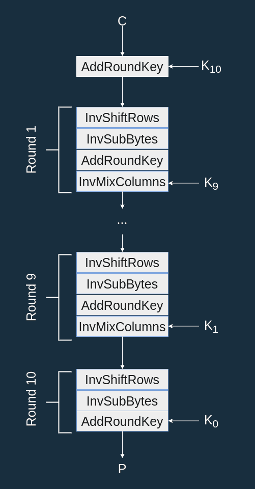
The inverted transforms being closely related to the original transforms, we will not elaborate on their behavior in this article.
Though, the interested reader can find their implementations using the following links.
Testing#
In order to test the correctness of our AES implementation, our test bench compares the result of our simulation against the output of a golden model coded in C.
For more information, as well as instructions on how to run the test bench, please see the README.
Resources#
If after reading this article, the reader desires a more in depth explanation of the AES algorithm, I would recommend reading the excellent write-up on this topic at braincoke. In particular the articles covering :
Official AES specification, link to pdf : Federal Information Processing Standard Publication 197 - Specification for the ADVANCED ENCRYPTION STANDARD (AES)