Introduction#
One of my current projects is to build the Ethernet physical layer for 10Gb (10GBASE-R) and 40Gb (40GBASE-R) fiber. In order to create a testbench I went out and bought a decommissioned Redstone D2020 enterprise switch off ebay.
Although there is practically no documentation on this switch and I have no prior experience working with any network equipment whatsoever, it was cheap and I believed that troubleshooting a system was a great opportunity to acquire that missing experience.
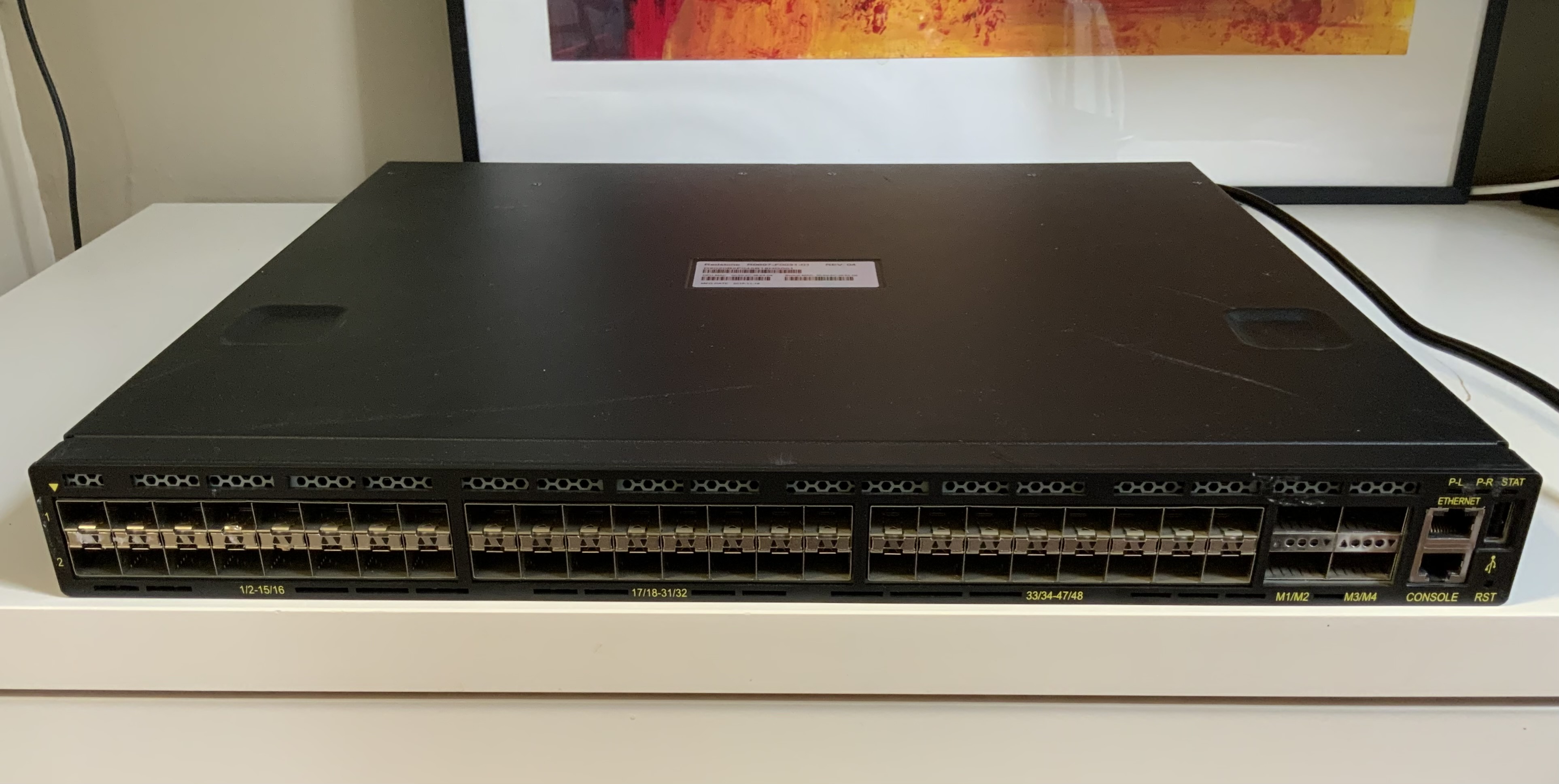
2 weeks later, this beauty showed up !
I am writing this article to document my experience, and in the hope that it may be useful to future owners of a Redstone D2020.
Celestical Redstone D2020#
The Celestica Redston D2020 is an 1U data center switch with 48 10GbE SFP+ capable ports and 4 QSFP+ 40GbE capable ports. It has two 460W power supplies for redundancy, 5 cooling fans, 1 Ethernet RJ45, 1 console RJ45 and 1 USB type A port.
Another big additional selling point is that, unlike some other models, it doesn’t require any license to operate.
I got mine off from UNIXSurplusNet on ebay for 150$.
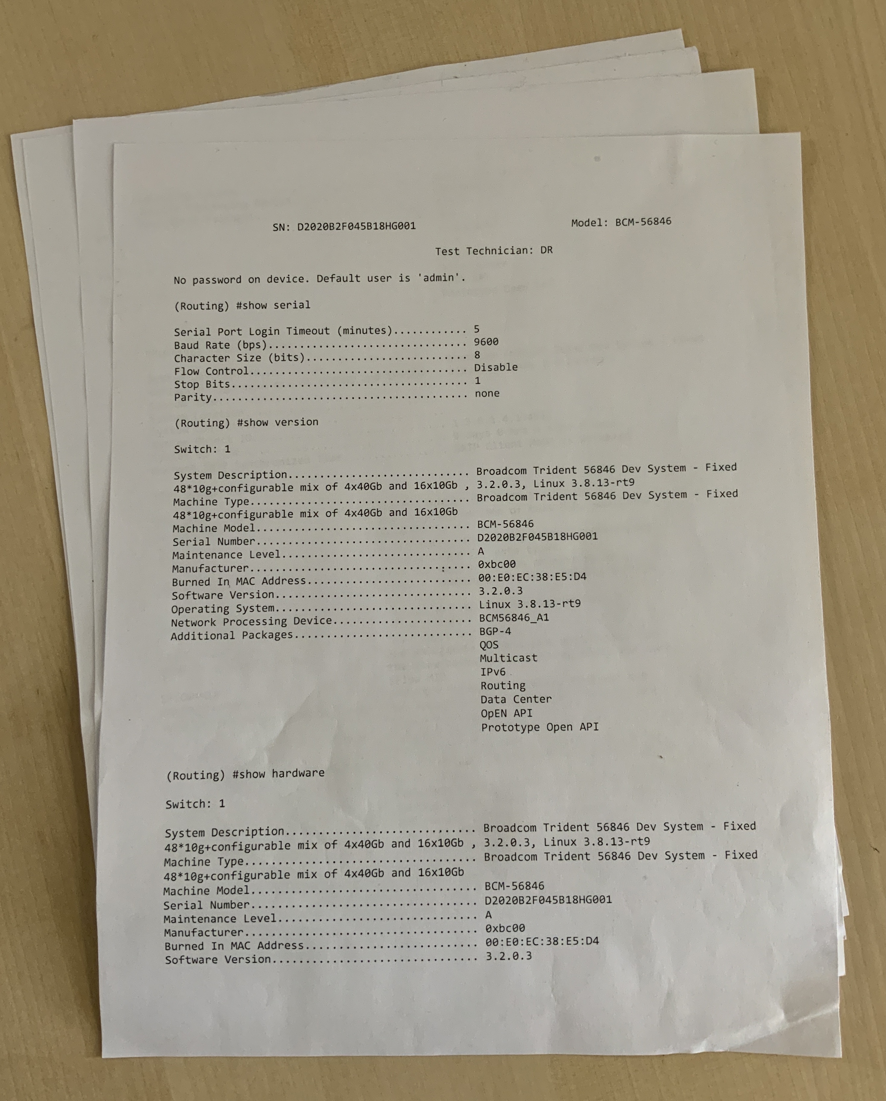
The sell provided a test report mentioning some very handy information such as the admin username and password, as well the console serial configuration, and as some general system information.
Ethernet ASIC#
Thanks to the seller-provided test report we learn that the main IC is showing up as a Broadcom Trident 56846.
This is probably of the first Trident generation, the BCM56846KFRBG of the Broadcom BCM56840 family that has since been discontinued.
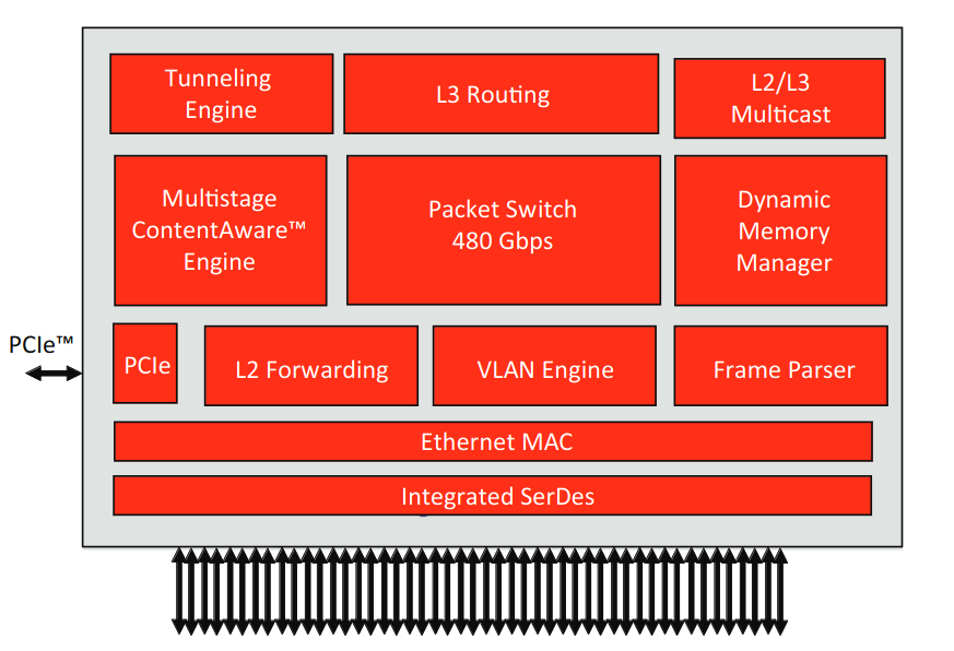
This appears to be a custom Broadcom ASIC targeting 10Gb Ethernet applications with 64 integrated 10GBASE-KR capable serial PHY’s.
In our switch 16 of these modules are configured, such that 4 lanes are bounded together, to form our 4 40GBASE-R ports.

I was unfortunately unable to find a full data-sheet describing this IC’s internals in detail.
As such, I did the next best thing I could think of…
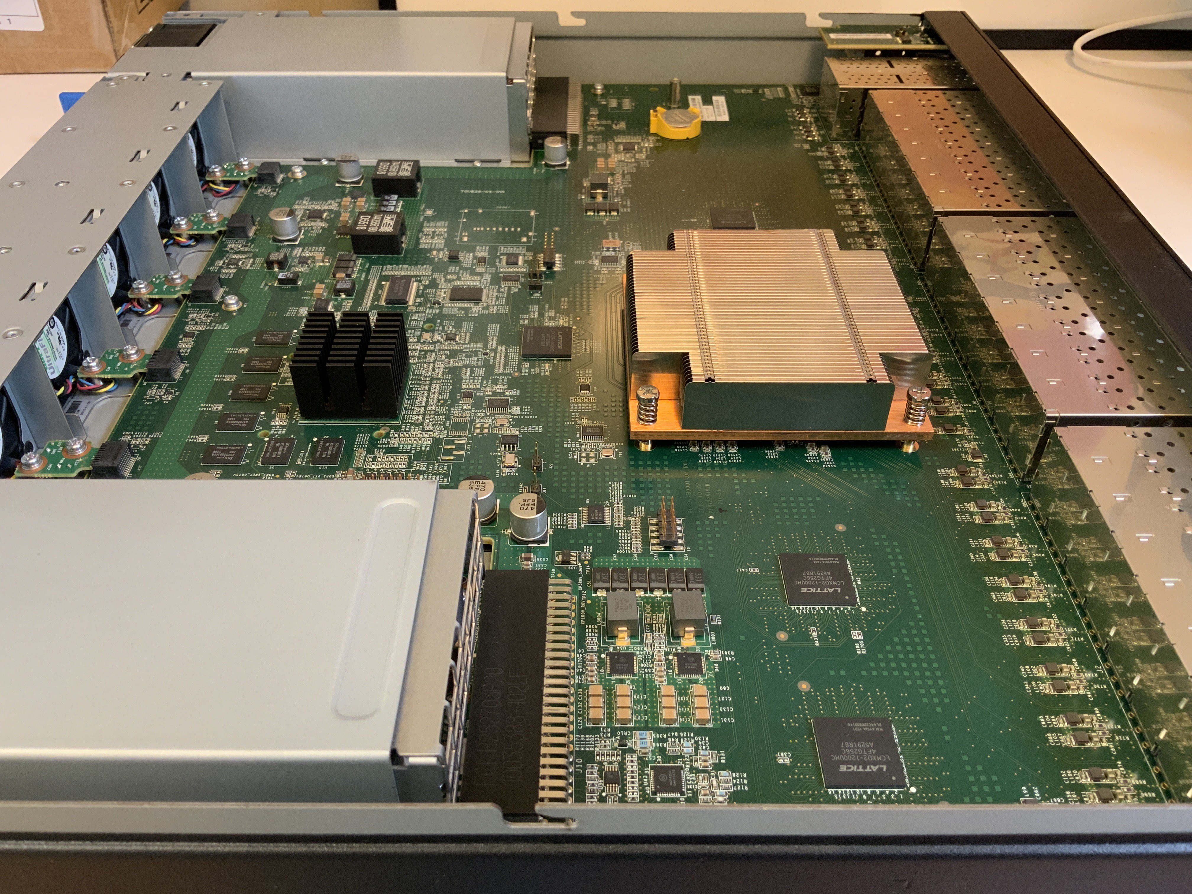
Pooping the lid open, we discover a single gorgeous multilayer PCB.
Judging by the traces on the PCB coming from the Ethernet connectors cages, the Broadcom IC is likely under the massive passive cooling block.
Looking at the product brief it appears this Broadcom IC doesn’t feature an CPU, rather it acts as a network interface connected to the CPU via PCIe.
CPU#
Our system’s CPU is likely located below the block cooling block as hinted by the DDR3 Sk hyinx memory chips surrounding another imposing black passive cooler.
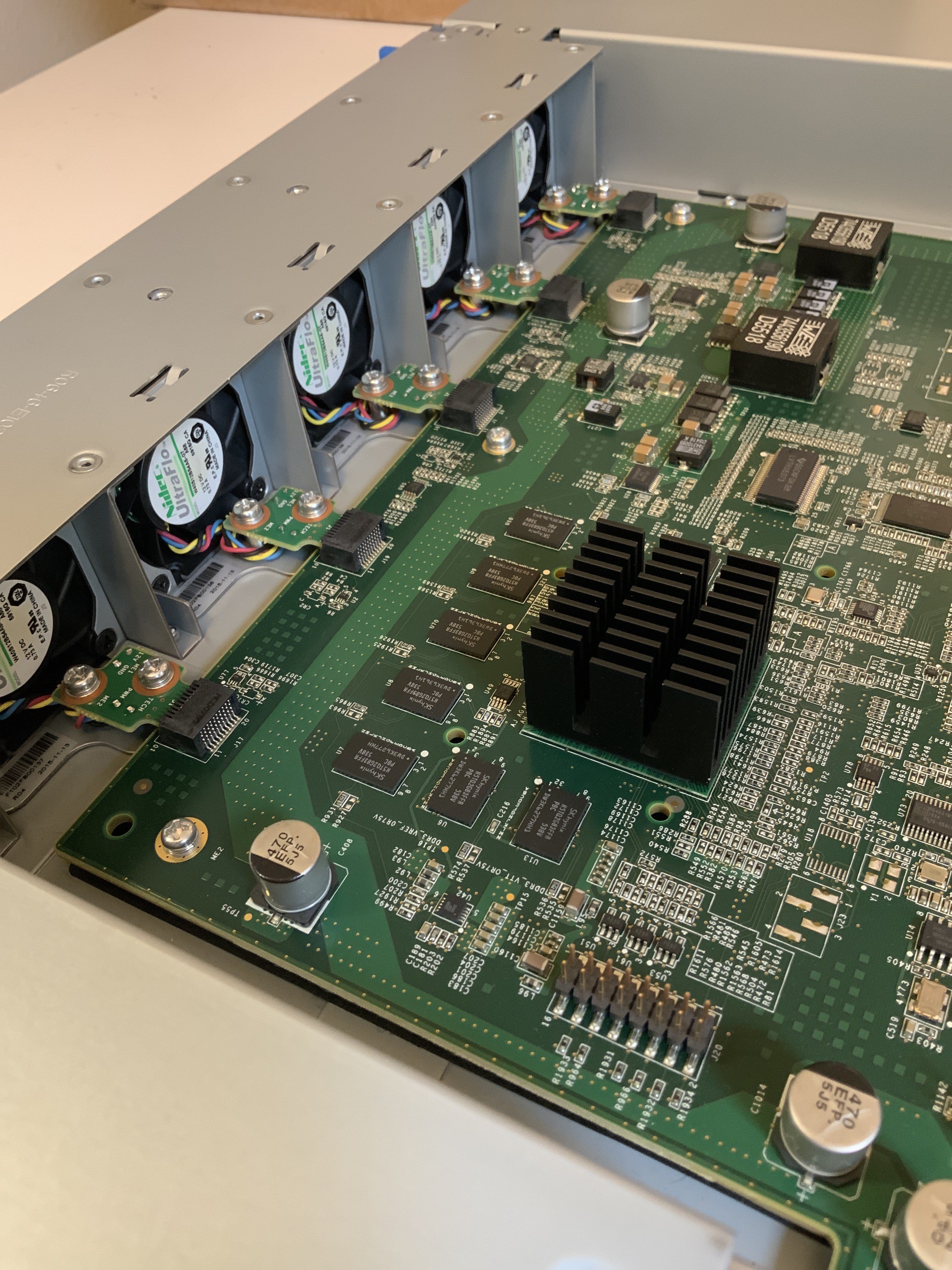
Our processor’s chip is a Freescale P2020, this is a dual core PowerPC system with 2GB of external EEC DDR3 DRAM.
Here we can notice an interesting inconsistency : the switch data brief
lists the CPUs as running at 800MHz,
but when we read the contents of /proc/cpuinfo the cores are reported as running at 1.2GHz.
# head -n 20 /proc/cpuinfo
processor       : 0
cpu             : e500v2
clock           : 1199.999988MHz
revision        : 5.1 (pvr 8021 1051)
bogomips        : 100.00

processor       : 1
cpu             : e500v2
clock           : 1199.999988MHz
revision        : 5.1 (pvr 8021 1051)
bogomips        : 100.00

total bogomips  : 200.00
timebase        : 50000000
platform        : P2020 CEL
model           : fsl,P2020
Memory          : 2048 MB
Power and cooling#
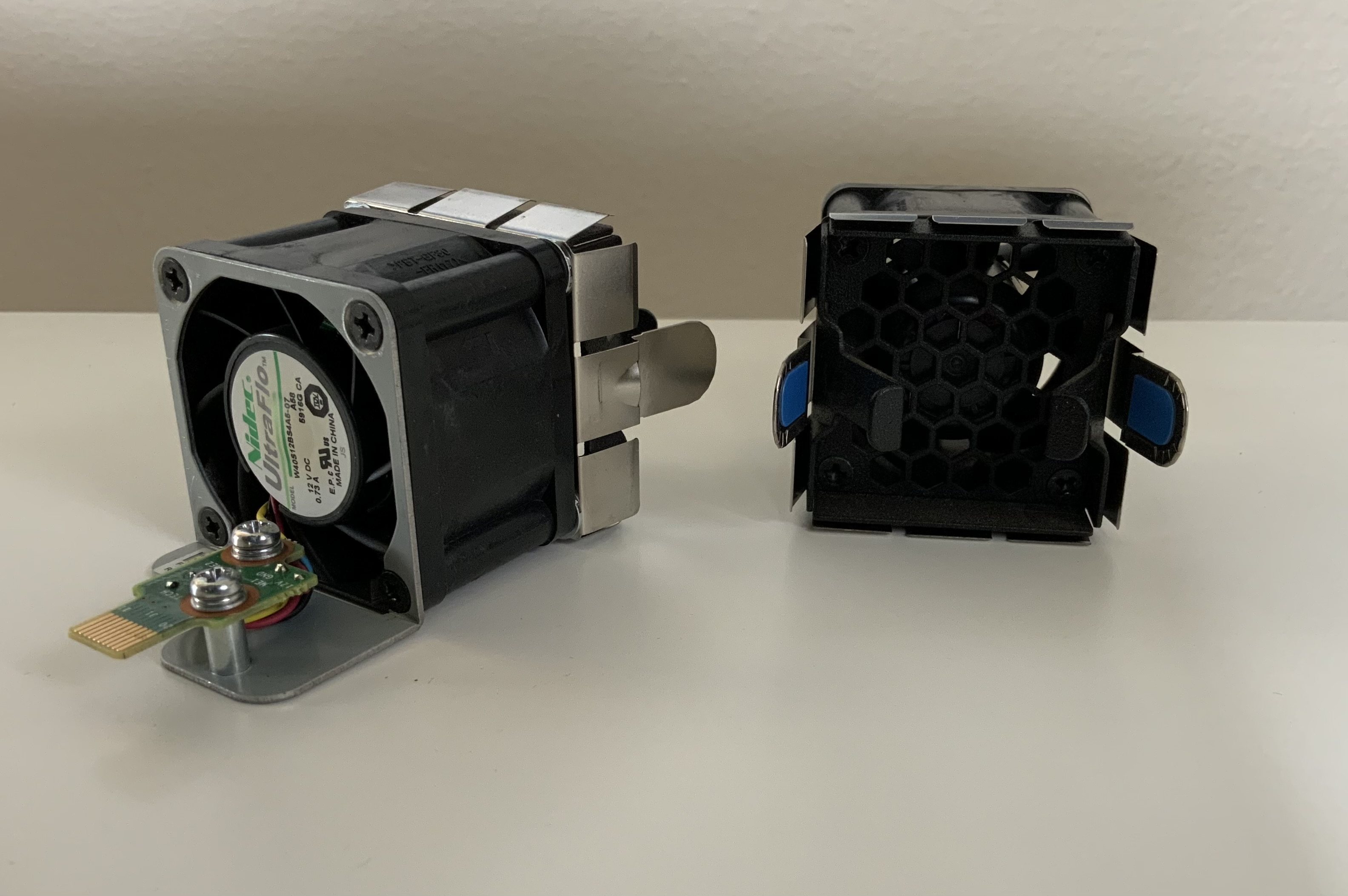
Behind the processor we have a series of cooling fans flanked on both sides by our power blocks.
Both the power blocks and the 5 fans have connectors to the PCB making them detachable. The fans can be easily detached, and come off as a single block. In practice only 4 fans are needed for operation, the 5th is redundant, so that one fan block can safely be removed at any time during operation.
Same goes for the power block, only one the 460W bricks is needed to power the switch, even at maximum load.
FPGA#
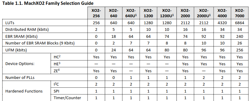
Interestingly this PCB also features 4 Lattice FPGAs of the MachXO2 family.
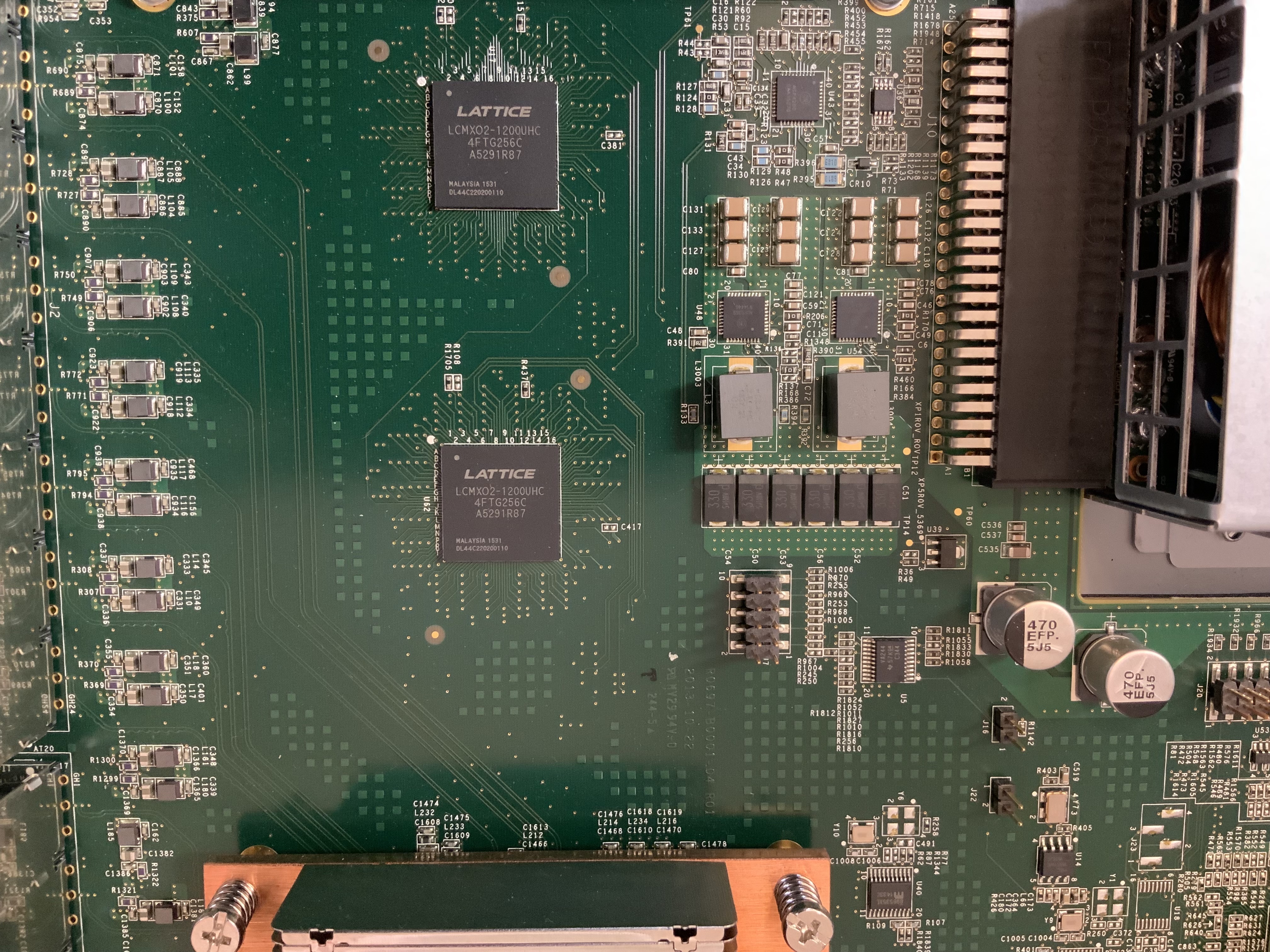
LCMX02-1200UHC FPGA on the PCB.These are relatively small FPGAs with only about 1280 LUTs each and are likely used as I2C bus controllers for accessing the Digital Diagnostic Monitoring Interface (DDMI) on the optical transceivers.
XO2-1200U in our switchFor those unfamiliar with optical transceivers, this interface allows real time access to the transceiver’s operating parameters, and it includes a system of alarm and warning flags which alerts the host system when particular operating parameters are outside of a factory set normal operating range. Additionally this also includes information the transceiver itself, such as the vendor, its laser wavelength, its supported link length, and more.
Internally each transceiver features an small microcontroller in charge of reporting this diagnostic information and communicates data to the wider system via the 2-wire serial I2C bus.

Since an I2C bus is a shared medium and multiple transceivers are connected onto the same I2C bus the FPGA acts as the I2C Master of this bus, as well as the controller for allowing the Broadcom Ethernet ASIC to interface with the I2C bus.
Thanks to this we can obtain information on the internal status of our connected transceivers.
Commands like show fiber-ports optical-transceiver give us the latest internal operating
parameters as read by the transceiver’s internal microcontroller and reported over I2C to the system.
Using this command we can get information on the transceiver’s temperature, input and output signal strength and operating voltage.
(Routing) #show fiber-ports optical-transceiver all

                                    Output    Input
Port      Temp  Voltage  Current     Power    Power   TX     LOS
           [C]   [Volt]     [mA]     [dBm]    [dBm]   Fault
--------  ----  -------  -------   -------  -------   -----  ---
0/49      30.5    3.292      N/A    -4.737  -19.318   No     Yes
0/51      32.9    3.288      N/A    -4.665   -9.397   No     No

 Temp - Internally measured transceiver temperatures.
 Voltage - Internally measured supply voltage.
 Current - Measured TX bias current.
 Output Power - Measured optical output power relative to 1mW.
 Input Power - Measured optical power received relative to 1mW.
 TX Fault - Transmitter fault.
 LOS - Loss of signal.
Here I can see that one of my transceivers has a lost the signal and the received optical power Input Power (dBm) = -19.318 dBm
this might indicate I might have some dust in my optical connections
, or may just be a bad contact.
Commands like show fiber-ports optical-transceiver-info reports the content of
sections of the transceiver’s EEPROM and presents them in a readable format.
This includes the unit’s vendor, its serial numbers, part number and what 802.3
physical medium it is compliant with.
(Routing) #show fiber-ports optical-transceiver-info all

                         Link Link                                 Nominal
                       Length Length                                   Bit
                         50um 62.5um                                  Rate
Port     Vendor Name      [m] [m]  Serial Number    Part Number     [Mbps] Rev  Compliance
-------- ---------------- --- ---- ---------------- ---------------- ----- ---- ----------------
0/49     AVAGO            0   0    QF2606UK         AFBR-79EQDZ-JU1  10300   01 40GBase-SR4
0/51     AVAGO            0   0    QF1803PC         AFBR-79EQDZ-JU1  10300   01 40GBase-SR4
Here I have 2 40Gb transceivers compliant with IEEE 802.3 Physical Medium Dependant (PMD) type 40GBASE-SR4 as outlines in clause
86.
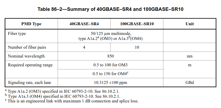
This is the 4 lane optical physical layer compatible with the 40GBASE-R4 PMA, the 40GBASE-R PCS,
which I am currently working on.
Connecting to the switch console#
My original plan was to gain access to the switch command line interface via the console port.
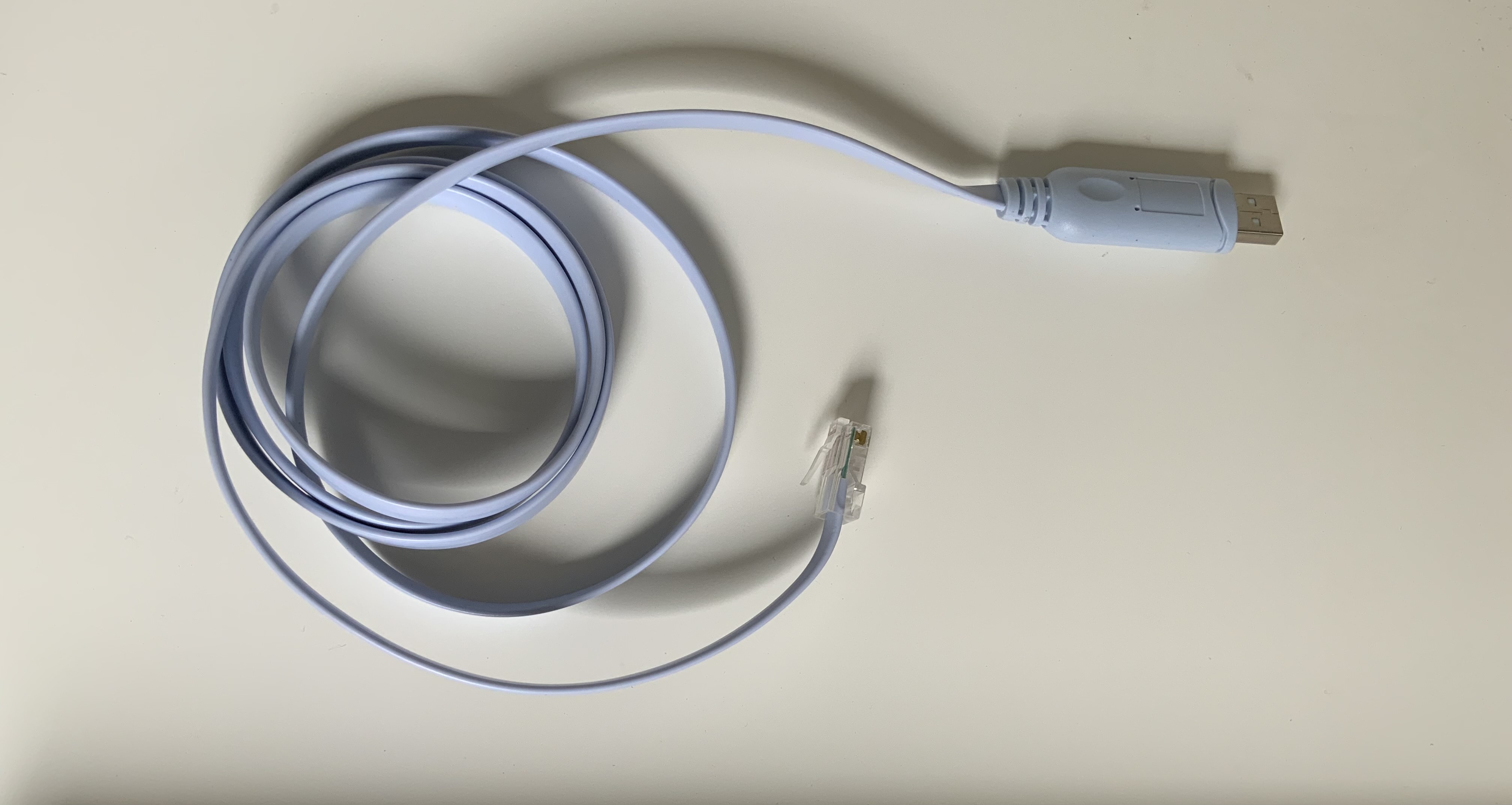
To this end, I had acquired an RJ45 to USB cable and configured my PC’s serial to match the seller-provided serial configuration.
(Routing) #show serial

Serial Port Login Timeout (minutes)............ 5
Baud Rate (bps)................................ 9600
Character Size (bits).......................... 8
Flow Control................................... Disable
Stop Bits...................................... 1
Parity......................................... none
Initially all seemed to be going well, the serial cable was correctly detected as an
USB to serial device, as evidenced by my dmesg logs.
pitchu /etc >sudo dmesg | tail
[55357.778160] usb 1-4: new full-speed USB device number 7 using xhci_hcd
[55357.931485] usb 1-4: New USB device found, idVendor=1a86, idProduct=7523, bcdDevice= 2.54
[55357.931501] usb 1-4: New USB device strings: Mfr=0, Product=2, SerialNumber=0
[55357.931503] usb 1-4: Product: USB2.0-Ser!
[55357.936519] ch341 1-4:1.0: ch341-uart converter detected
[55357.949546] ch341-uart ttyUSB0: break control not supported, using simulated break
[55357.949663] usb 1-4: ch341-uart converter now attached to ttyUSB0
I was using picocom as a serial terminal with a baud-rate of 9600B, no flow control, a character size of 8, 1 stop bit and no parity.
pitchu /dev/serial >sudo picocom -b 9600 /dev/ttyUSB0 --omap delbs
picocom v3.1

port is        : /dev/ttyUSB0
flowcontrol    : none
baudrate is    : 9600
parity is      : none
databits are   : 8
stopbits are   : 1
escape is      : C-a
local echo is  : no
noinit is      : no
noreset is     : no
hangup is      : no
nolock is      : no
send_cmd is    : sz -vv
receive_cmd is : rz -vv -E
imap is        :
omap is        : delbs,
emap is        : crcrlf,delbs,
logfile is     : none
initstring     : none
exit_after is  : not set
exit is        : no

Type [C-a] [C-h] to see available commands
Terminal ready
Yet, nothing happened. There was never any response from the console port. It was as if I was sending commands into the void .
Even after trying multiple different serial terminals such as minicom and screen as well as
trying different serial configurations I didn’t seem to find a way to successfully connect to the switch.
Was there something wrong with the switch, was it not booting properly ?
Checking switch liveness#
At this point the switch was powered and connected via its console port to my PC but it was not connected to my network.
Although the fans were spinning and I had some blinking, I wanted to check if the switch systems had been successfully started.
I connected the RJ45 management port directly to my PC and started scanning network traffic on this link using wireshark.
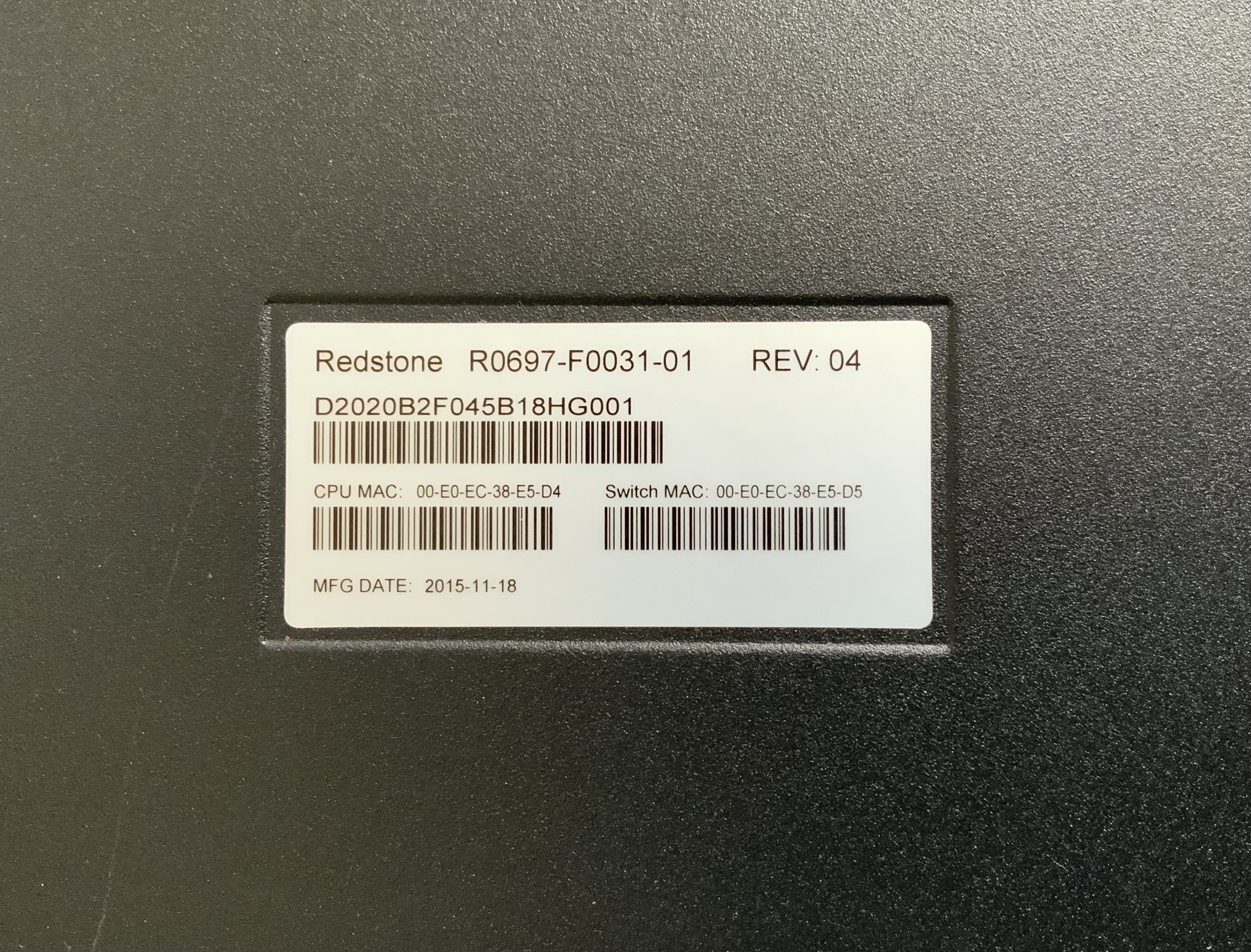
For context, within the first 3 bytes of the MAC address, 22 bits are reserved for the equipment vendor’s identifiers, and Celestica has the vendor identifier 0x00e0ec.
Our switch’s MAC address is 00:e0:ec:38:e5:d5.
After a little while an ICMP message originating from the MAC address 00:e0:ec:38:e5:d5 was captured.
We can spot our switch’s MAC address as the source MAC in the packet’s MAC header.
0000   33 33 00 00 00 16 00 e0 ec 38 e5 d5 86 dd 60 00   33.......8....`.
                         ^^ ^^ ^^ ^^ ^^ ^^
0010   00 00 00 24 00 01 00 00 00 00 00 00 00 00 00 00   ...$............
0020   00 00 00 00 00 00 ff 02 00 00 00 00 00 00 00 00   ................
0030   00 00 00 00 00 16 3a 00 05 02 00 00 01 00 8f 00   ......:.........
0040   89 7c 00 00 00 01 04 00 00 00 ff 02 00 00 00 00   .|..............
0050   00 00 00 00 00 01 ff 38 e5 d5                     .......8..
This confirmed that our switch was indeed working correctly, so now we just needed to find another way in.
Telnet#
Since I now had proof that the switch was working properly, and that the basic networking features were running as evidenced by the ICMP packet
I decided to check if there wasn’t also an ssh port open.
At this point I connected the switch to my home’s router and started scanning my network using nmap, to see if the switch had an assigned IP.
pitchu /dev/serial >nmap -sn 192.168.4.0/24
Starting Nmap 7.94 ( https://nmap.org ) at 2023-10-03 16:13 PDT
Nmap scan report for 192.168.4.1
Host is up (0.018s latency).
Nmap scan report for 192.168.4.22
Host is up (0.0075s latency).
Nmap scan report for 192.168.4.81
Host is up (0.00045s latency).
Nmap scan report for 192.168.4.106
Host is up (0.015s latency).
Nmap done: 256 IP addresses (4 hosts up) scanned in 3.09 seconds
The switch’s address was 192.168.4.106, and I then proceeded to check what ports were open.
pitchu /dev/serial >nmap --top-ports 1000 192.168.4.106
Starting Nmap 7.94 ( https://nmap.org ) at 2023-10-03 16:16 PDT
Nmap scan report for 192.168.4.106
Host is up (0.0039s latency).
Not shown: 998 closed tcp ports (conn-refused)
PORT   STATE SERVICE
23/tcp open  telnet
80/tcp open  http

Nmap done: 1 IP address (1 host up) scanned in 0.19 seconds
Initially I had hoped for an open ssh port, telnet can also provide access to a virtual terminal.
Although telnet is sometimes considered as lesser compared to ssh because it is less secure, for
my local test oriented use case it is just as good.
I then opened a telnet connection and logged into the admin user session.
pitchu /dev >telnet 192.168.4.106 23
Trying 192.168.4.106...
Connected to 192.168.4.106.
Escape character is '^]'.

User:admin
Password:
(Routing) >
Success, we are in :partying_face:
Getting access to linux shell#
When connecting to the switch, by default we log into a networking specific command line interface and not a linux shell. This CLI is very similar to the one used by Dell for there S4048-ON System.
By entering the ? character was can view all available commands.
(Routing) >?

enable                   Enter into user privilege mode.
help                     Display help for various special keys.
logout                   Exit this session. Any unsaved changes are lost.
password                 Change an existing user's password.
ping                     Send ICMP echo packets to a specified IP address.
quit                     Exit this session. Any unsaved changes are lost.
show                     Display Switch Options and Settings.
telnet                   Telnet to a remote host.
By default we are logged in an unprivileged session, as signified by the > in out prompt.
We can elevate our privilege level, using the enable command, this also expands
our available commands.
We can also confirm that we have entered privileged mode thanks to the # in our prompt.
(Routing) >enable

(Routing) #?

application              Start or stop an application.
arp                      Purge a dynamic or gateway ARP entry.
bcmsh                    Enter into BCM Shell
boot                     Marks the given image as active for subsequent
                         re-boots.
cablestatus              Isolate the problem in the cable attached to an
                         interface.
capture                  Enable CPU packets capturing.
clear                    Reset configuration to factory defaults.
configure                Enter into Global Config Mode.
copy                     Uploads or Downloads file.
debug                    Configure debug flags.
delete                   Deletes the given image or the language pack file.
dir                      Display directory information.
disconnect               Close remote console session(s).
dot1x                    Configure dot1x privileged exec parameters.
enable                   Set the password for the enable privilege level.
erase                    Erase configuration file.
exit                     To exit from the mode.
filedescr                Sets text description for a given image.
help                     Display help for various special keys.
hostname                 Change the system hostname.
ip                       Configure IP parameters.
linuxsh                  Enter into Linux Shell
logout                   Exit this session. Any unsaved changes are lost.
network                  Configuration for inband connectivity.
ping                     Send ICMP echo packets to a specified IP address.
quit                     Exit this session. Any unsaved changes are lost.
release                  To release IP Address.
reload                   Reset the switch.
renew                    To renew IP Address.
script                   Apply/Delete/List/Show/Validate Configuration Scripts.
serviceport              Specify the serviceport parameters / protocol.
set                      Set Router Parameters.
show                     Display Switch Options and Settings.
snmp-server              Configure SNMP server parameters.
sshcon                   Configure SSH connection parameters.
telnet                   Telnet to a remote host.
telnetcon                Configure telnet connection parameters.
terminal                 Set terminal line parameters.
traceroute               Trace route to destination.
udld                     Reset UDLD disabled interfaces.
vlan                     Type 'vlan database' to enter into VLAN mode.
watchdog                 Enable/Disable/Clear watchdog timer settings.
write                    Configures save options.
Unfortunately, this is a dedicated CLI and I would like to have access to the full linux shell.
Now that we are in privilege mode we can escape this CLI and access the linux shell by using linuxsh.
(Routing) #linuxsh
Trying 127.0.0.1...

Connected to 127.0.0.1


Linux System Login

# pwd
/mnt/application
To recap :
I now felt right at home.
Reducing the noise#
At idle the fan duty cycle is set to 60%, stated otherwise : this switch is cosplaying as a jet engine. :rocket:
Obviously this isn’t going to fly.
The first order of business is to make the noise a little more bearable.
I can reduce the fan’s PWM by overwriting the contents of /sys/class/thermal/manual_pwm. This
value is bound within the [0;255] range.
It is apparently advised to keep the temperature of all internal components of the switch below 50 degrees Celcius.
So far a ~15% duty cycle seems to be a good compromise given my use case.
# echo 40 > /sys/class/thermal/manual_pwmCheck thermals#
To check thermals, either exit linuxsh using the exit command and check the equipment’s status using show environment :
# exit

Connection closed by foreign host.
(Routing) #show environment

Temp (C)....................................... 37
Fan Speed, RPM................................. 3181
Fan Duty Level................................. 16%
Temperature traps range: 0 to 45 degrees (Celsius)

Temperature Sensors:
Unit     Sensor  Description       Temp (C)    State           Max_Temp (C)
----     ------  ----------------  ----------  --------------  --------------
1        1       lm75_p2020        30          Normal          30
1        2       lm75_bcm56846     37          Normal          39
1        3       lm75_LIA          32          Normal          32
1        4       lm75_RIA          27          Normal          27
1        5       lm75_ROA          26          Normal          26
1        6       lm75_psuinlet1    27          Normal          33
1        7       lm75_psuinlet2    26          Normal          26

Fans:
Unit Fan Description    Type      Speed         Duty level    State
---- --- -------------- --------- ------------- ------------- --------------
1    1   Fan-1          Removable 3181          16%           Operational
1    2   Fan-2          Removable 3186          16%           Operational
1    3   Fan-3          Removable 3171          16%           Operational
1    4   Fan-4          Removable 3215          16%           Operational
1    5   Fan-5          Removable 3178          16%           Operational

Power Modules:
Unit     Power supply   Description        Type          State
----     ------------   ----------------   ----------    --------------
1        1              PS-1               Removable     Operational
1        2              PS-2               Removable     Operational
Or read the contents of the *_temp files in the /sys/class/thermal folder.
# cd /sys/class/thermal/
# ls
LIA_temp        bcm56846_temp   fan3speed       manual_pwm      psu2_status
RIA_temp        fan1speed       fan4speed       p2020_temp      psuinlet1_temp
ROA_temp        fan2speed       fan5speed       psu1_status     psuinlet2_temp
Since cat is not installed by default, I am using head as a replacement to quickly read those files.
# head ROA_temp
28
Scripts are removed at reboot#
I had written a small script to rewrite the fan’s PWM after boot, which I had named rc.local and placed in /etc/init.d with execute permissions.
#!/bin/sh
echo 30 > /sys/class/thermal/manual_pwm
exit 0
This script was confirmed to be working when invoked via shell.
Unfortunately after reboot not only did the changes not take effect but the script was gone.
This may be a symptom that the root file system is getting mounted at boot from an image, and since I am modifying the mounted version and not the original one, my changes are not permanent. Finding a workaround for this will be the subject of a later post.
Closing remarks#
From initially getting what amounted to a black box and having no networking equipment knowledge. I now have a working switch, a better understanding on the internals of this switch, a root access to its linux shell and have upgraded up my network-equipment-related knowledge through troubleshooting and experimentation.
Moving forward I plan to continue looking for a way to reset PWM fan speed after boot, start experimenting by
writing a few static routing tables, and maybe open an ssh tunnel to replace telnet.
I would like to thank EmbeddedKen for helping me figure out the use of the Lattice FPGAs, ThomasC and reddit user bvcb907 for their very insightful answers from 3 years ago on the reddit thread related to this switch.
Resources#
Digital Diagnostic Monitoring Interface for SFP and SFP+ Optical Transceivers
Reddit : Redstone D2020 48x 10GbE SFP+ & 4x QSFP Switch???
Is Broadcom’s chip powering Juniper’s Stratus?
HIGH-CAPACITY STRATAXGS® ETHERNET SWITCH FAMILY WITH INTEGRATED 10G SERIAL PHY
QorIQ® P2020 and P2010 Dual- and Single-Core Communications Processors
List of MAC addresses with vendor identifiers.
Dell Command Line Reference Guide for the S4048–ON System 9.14.2.5